The C.N.R. Project

The
C.N.R. Project
The Chung's Negative Resistance experiment
Created on 05-20-01 - JLN Labs
- Last update 06-19-01
All informations in this
page are published free and are intended for private/educational
purposes and not for commercial applications
<< In a July 9, 1998, at the 5th International Conference on Composites Engineering in Las Vegas, Dr. Deborah D. L. Chung, professor of mechanical and aerospace engineering at University at Buffalo (UB), reported that she had observed apparent negative resistance in interfaces between layers of carbon fibers in a composite material. Professor Chung holds the Niagara Mohawk Chair in Materials Research at UB and is internationally recognized for her work in smart materials and carbon composites. The negative resistance was observed in a direction perpendicular to the fiber layers. A paper describing the research was submitted by Chung to a peer-reviewed journal, and a patent application was filed by the University. >> Document source "On Extracting Electromagnetic Energy from the Vacuum," IC-2000, by Tom Bearden
Now, On May 19th, 2001, I have been able to replicate successfully the Chung's Negative Resistance (CNR). You will find in these pages all informations and datas about the CNR experiment that I have done. The CNR experiment has been conducted so as to be closer to the original Chung's design which is fully described in the paper "Apparent negative electrical resistance in carbon fiber composites," by Shoukai Wang and D.D.L. Chung - Composites, Part B, Vol. 30, 1999, p. 579-590.
A) - Brief description of the CNR experiment conducted by D. Chung and S. Wang in 1998
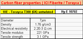
The original CNR design consisted in two 6 mm strips of 7 micrometer unidirectional carbon fiber which have been previously pressed ( at 1.4 MPa ) together and glued with epoxy cement in a crossply configuration to form a 6x6 mm junction.
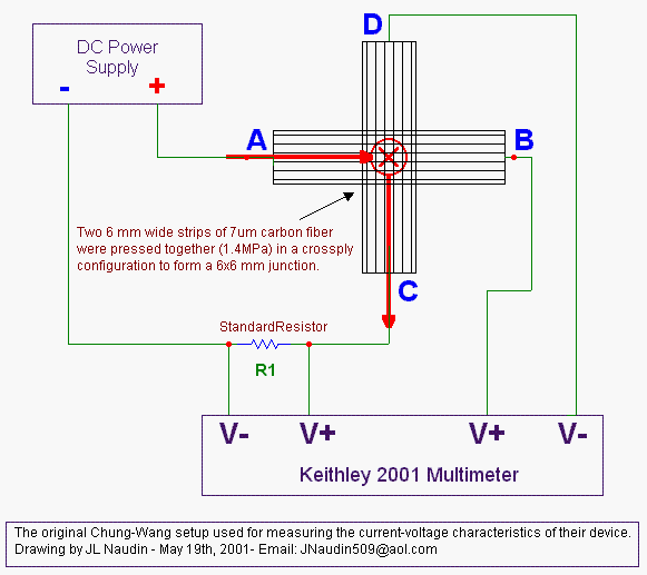
In the CNR diagram above, the top lamina is AB and the bottom lamina is CD. The voltage difference between the two laminas in the junction has been measured across B and C and the current flows from A to C with a standard resistor ( R1 ) connected in serie. A Keithley 2001 multimeter has been used during this experiment. The electrical current was calculated by Ohm's Law ( I = U(R1) / R1 ).
An apparent negative resistance has been measured at the junction : the current-voltage characterictic was a straight line with a negative slope through the origin. The electrons, in the junction, seemed to travel in the unexpected direction ( backflow ) according to the voltage gradient.
For more informations and technical datas read : "Apparent negative electrical resistance in carbon fiber composites," by Shoukai Wang and D.D.L. Chung - Composites, Part B, Vol. 30, 1999, p. 579-590.
B) - The JL Naudin's Negative Resistance experiment replication done on May 19th, 2001
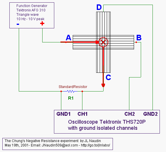
I have used a Tektronix Function Generator AFG-310. The point A has been connected to its positive output and the point E to its ground. The signal output has a triangular shape, a frequency of 0.1 Hz and 10 Volt Peak. The voltage measurements have been done with a Tektronix oscilloscope THS720 which has ground isolated channels. ( see the testing setup diagram below )
CNR v1.0 : TESTS
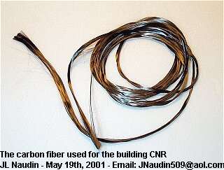
The first CNR v1.0 device has been built according to the description done in the Dr Chung's paper cited above. I have used two similar strips of carbon fiber (see the photo below ) glued with epoxy in a cross shape.
CNR v1.0 : tests results :
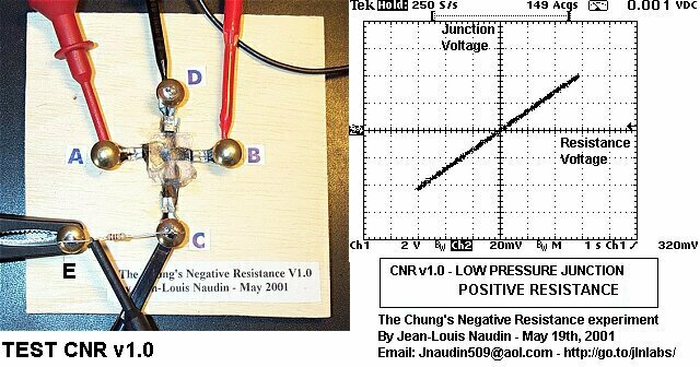
The slope of the Current-Voltage curve was POSITIVE and thus the measured resistance junction was POSITIVE. The measured current changed from -60mA to +60mA and the measured voltage across the CNR junction changed from -40mV to +40mV at a rate of 0.1 Hz.
The measured junction resistance between the carbon fiber strips was +0.667 ohms
Interesting notes : I have noticed that if I increase strongly the pressure of the carbon layers at the junction, I have been able to change the slope of the the current-voltage curve. I have been able to nullify the slope ( the junction resistance = zero Ohm ) and also to get a negative slope ( the junction resistance < 0 ). This has encouraged me to continue the investigation, and thus I have decided to build a new CNR device with a stronger junction pressure during the gluing phase...
CNR v2.0 : TESTS
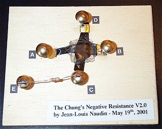
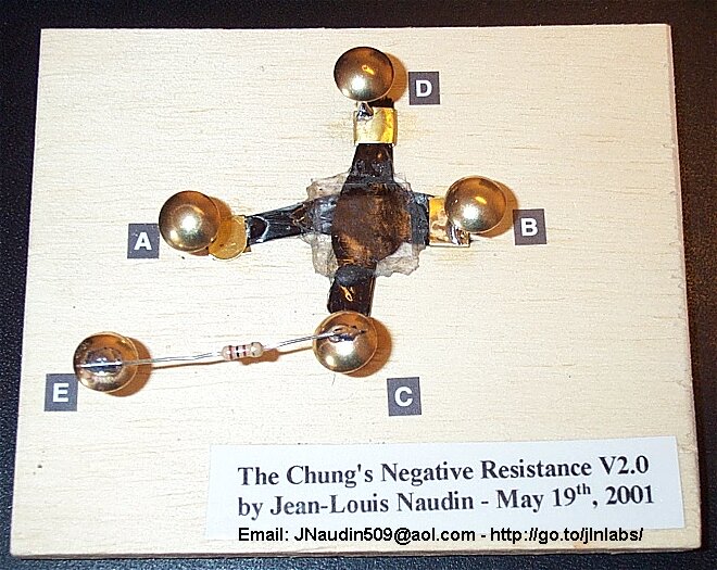
The first CNR v2.0 device has been built with the same method than the v1.0, but the junction pressure has been strongly increased comparing to the previous version during the gluing phase with the epoxy cement (see the photo below ).
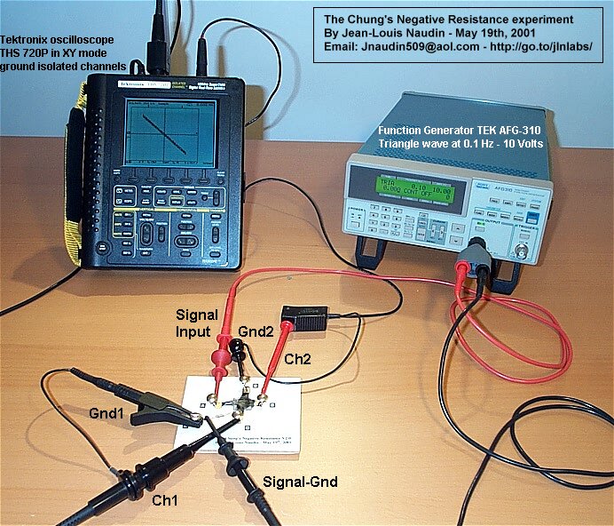
( Above ) Photo of the testing setup
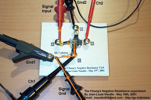
(Above) A detailled view of the CNR v2.0 under test, the orange line shows the current path
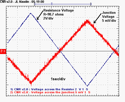
The red curve shows the voltage measured across CNR junction
The blue curve shows the voltage measured across Resistor ( R1=98.7
ohms ).
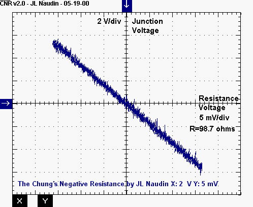
CNR v2.0 : tests results :
The slope of the Current-Voltage curve was NEGATIVE and thus the measured resistance junction was NEGATIVE. The measured current changed from -64mA to +64mA and the measured voltage across the CNR junction changed from -14mV to +14mV at a rate of 0.1 Hz.
The measured junction resistance between the carbon fiber strips was -0.218 ohm
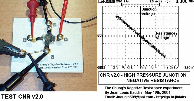
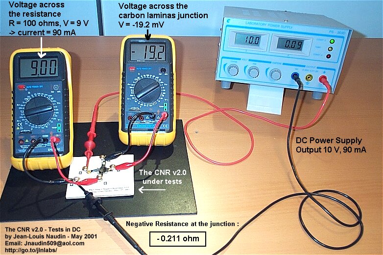
The negative resistance of the CNR junction has also been measured in DC
The results are now very encouraging, today, I can confirm experimentaly the "Negative Resistance" discovered by Dr. Chung in 1998.
It is interesting to know that Dr Chung and Wang have demonstrated negative resistance as low as -8 ohms for a contact area of one square centimetre.
The CNR is an "apparent"
Negative resistance rather than a true resistance. Its
mechanism seems equivalent to a true negative resistance
because the electrons flow in the unexpected direction
relative to the applied current/voltage and this occurs
only in the junction between the two carbon fiber
laminas, the XY section showed in my 3D diagram. The equivalent model
of the CNR can be easily simulated by a computer ( see the CNR simulation ) and
the interesting fact to observe is that a negative value
for the Rneg must be set for getting the same result than
the working unit. Dr Chung has said in his paper (1) : <<
The control of the relative amounts of the backflow and
forward flow means the control of the total apparent
resistance. In the situation of zero apparent resistance,
the two flows are nonzero but balanced, such that the
voltage across the flow region is zero. The current loops
in this region suggest the possibility of interesting and
electromagnetic effects. I shall keep you informed about my progress in this field of research through this web page : http://jnaudin.free.fr/cnr/. Thanks you very much to all for your
encouragements and your helpful support. |
Documents references and Press releases :
Patents :
Carbon Fibers :
For
more informations, please contact : ![]() JNaudin509@aol.com
JNaudin509@aol.com
Return to the CNR home page