Throughts about the MEG principle
By Cyril Smith
created on 11-01-00 - JLN Labs - last update on 11-01-00
| Subject : | MEG thoughts |
| Date : | 30/10/00 22:49:12 Paris, Madrid |
| From: [email protected] (Cyril Smith) | |
Hi All,
I have re-read Bearden's paper in the light of the latest information.
There are some aspects I agree with, sort of. Like his decomposition of any scalar potential into a set of harmonic EM wavepairs travelling in opposite directions, one being the phase conjugate of the other. Anyone who has studied transmission lines, and in particular standing waves, will appreciate this. However my views on EM waves as bunches of sub photon particles leads me to the view that the scalar potential at a point in space comes from these particle beams arriving from opposite directions, carrying the EM wave pattern: even DC as in electrostatics involves a non random pattern. The pattern is imposed by the boundary conditions. But even with no pattern the particles are there in random fashion, and I see this as the giant negentropy source.
Bearden emphasises the different fields, the B field in the core and the A field outside it. He then talks about the coil extracting energy separately from these fields, as though the two forms of extraction are different. But in my book the only way the coil can extract energy from the B field is via the A field, Bearden does not seemed to have made that link. So I have misgivings about Bearden's explanation, but I am prepared to believe that the device does work.
Having given some thought to the way the new exotic materials behave as giant Barkhausen jumps, tiny input H creates giant B change by way of all the dipoles in the sample reversing direction, and the way the domain wall travels through the material at some relatively low velocity (cf the velocity of light), I have come up with a suggestion for a magnetic OU device which might be similar to the MEG.

In the first gif the top drawing shows the MEG core straightened out, the arrows showing the atomic dipole orientations due to the PM. The bottom drawing shows the dipoles switching polarity as a result of current in the drive coil on the left. There is a domain wall travelling left to right. When it reaches the magnet on the right the core is completely magnetised in the one direction, the inductor is fully charged. We could discharge the inductor and regain the input energy, but we are interested in OU so we want some form of reflected wavefront to augment the discharge. Unlike EM waves which can travel through each other without interference, we cannot have domain walls travelling in opposite directions in the same sample. So let's try two samples.

The second gif shows two cores with coils wound round both. Current in the coil on the left sends the wavefront down one core only because the other is already saturated in that polarity. The wavefront is shown having reached the other coil. When this wavefront reaches the shorted coil on the right the Lenz reaction from induced currents causes the dipoles in the other core to switch, thus sending a domain wall wavefront back along the second core. If the first coil is discharged in synchronism with the arrival of the return wavefront the energy extracted will be greater than the energy input, since there will be greater flux change.
Although shown as long rods, the same argument applies to the ring core MEG situation, you just have to juggle the manner in which coils wound on each segment are interconnected.
Any comments?
Cyril Smith
| Sujet : | MEG |
| Date : | 01/11/00 17:40:55 Paris, Madrid |
| From:
[email protected] (Cyril Smith) To: JNaudin509@aol.com |
|
Hi All, Jean Louis,
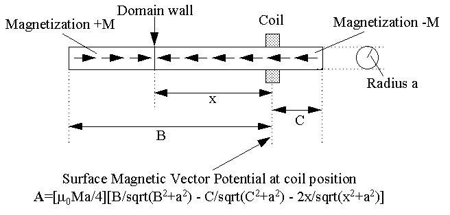
I have looked at the magnetic vector potential at a fixed point
on a core, and how it changes when a domain wall is approaching.

The gif above shows a cylindrical core of radius a and length B+C, with a coil positioned at station C from one end. A domain wall is at distance x from the coil. I give the formula for calculating vector magnetic potential A at the coil position, and of course the A field lines form closed circles around the core. It is a simple matter to increment the wall along at the wall velocity to produce a plot of A v. time, then to differentiate A to get E whose closed line integral is the induced voltage. The formula ought to apply to a ring core using arc dimensions in place of the linear ones.
I have played with this on a spreadsheet to plot the induced voltage impulse. A core whose radius is small cf its length gives a narrow impulse something like a gaussian pulse. The 1/2 amplitude width of the gaussian is approximately 4a/v seconds where v is the domain velocity. An interesting observation, increasing the radius a increases the width of the pulse, but the peak voltage remains constant.
Regards
Cyril Smith
![]() [email protected]
[email protected]
Read the next paper from Cyril Smith
Return to the MEG project home page