The Nicolay Zaev Generator
A Simulated model by Jean-Louis Naudin
Created on 10-25-98 - JLN Labs - Last update 10-28-98
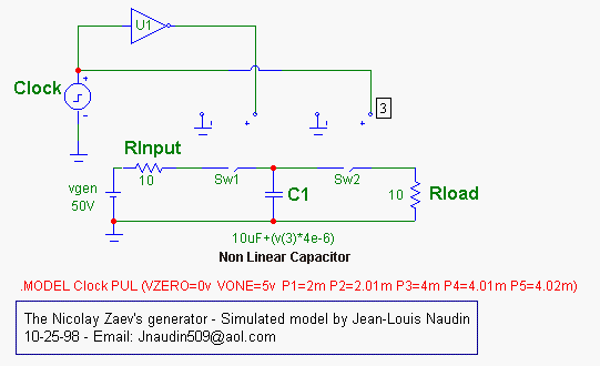
In this document I have tried to simulate with the Microcap V electronic software simulator, the basic functionning of the Zaev's generator. This device use a nonlinear capacitor as C1. The Clock ( a square wave generator ) is used for the control of the switches SW1 and SW2 which handle the Charge/Discharge sequence of the capacitor C1.

You may download the MC 5.20 model ( 8kb) and test by yourself this circuit

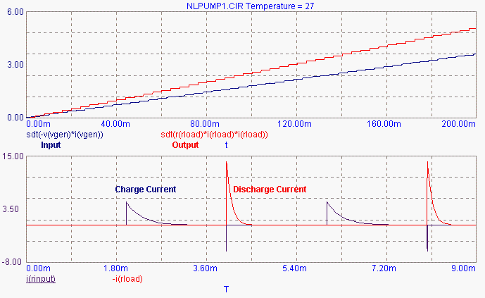
The first diagram above, shows the integral of power I/O with respect to T (Time in ms):
The blue curve shows the integral of the INPUT Power ( including the joules losses ) with respect to time,
The red curve shows the integral of the OUTPUT Power with respect to time,
You main notice that the red curve is always above the blue curve, this demonstrate that the total energy output will be always greater than the energy (COP>1) delivered by the power supply ("vgen" in the diagram).
The second diagram shows the current flow accross the Rinput and the Rload during the charge/discharge sequence of the nonlinear capacitor C1.
This model seems to be in agreement with the principle claimed and observed by Nicolay Zaev. Now, the main objective is to find a kind of nonlinear capacitor for building working generator.....
Jean-louis Naudin
![]() Email
: [email protected]
Email
: [email protected]
Return to the Zaev's Generator page or JLN Labs home page