The HF
TRANSFORMER Experiment
by Milan Manchich
Created on 06-21-01
- JLN Labs - Last update 06-22-01
All informations in this
page are published free and are intended for private/educational
purposes and not for commercial applications
![]() See the
latest update 07-01-01 : HF
Transformer - Part 2
See the
latest update 07-01-01 : HF
Transformer - Part 2

There are two ways of trawelling waves (HF; longitudinal waves) propagation in coax cable. Open and closed circuit propagation. In the first case we have max. current on the 0.25 wave length, which is analogy of the serial connection of L-C circuit. In the second case we have min. current on the 0.25 wave length, which is analogy of the paralell connection of L-C circuit.
This was the base of my HF Transformer.
For this transformer we can use ordinary bifilar coil or flat ,spiral bifilar coil, like Tesla did and presented in his patent No.512 340.
The Only difference is that we are not using common terminal of coils. We will treat the coils like a capacitor.
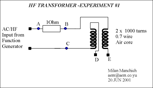
We can use AC/HF input or DC pulses . See pictures below :

According to the pictures above, we have two free terminals.
Fisrt step is to find resonant frequency for this coil/capacitor When we found resonant frequency we have max. current from power source.
But we have high voltage on the free terminals. Value of voltage and current depends of L-C parameters. When we make short connection between the free terminals we will notice current drop from the power source. This is a second case of longitudinal waves propagation with min. current. There is no point using just this coil like a transformer. But if we add a capacitor for collecting high voltage we can notice several strange and interesting effects which I will describe in more details...
Milan Manchich
June 21, 2001
[email protected]
HF TRANSFORMER : 1st serie of experiments
BASIC CIRCUIT


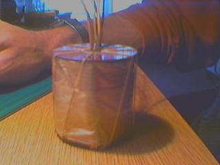
COIL
:
EQUIPMENTS :
|

BELOW
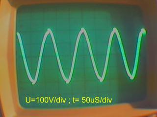
: CURRENT "A"-"B", VOLTAGE "B"-"C"
Please notice how voltage curve looks like. It is similar what
Ron Cole has with Bedini motor voltage output.

Below
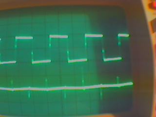
: SHORT CONNECTED TERMINALS "D" AND "E"
VOLTAGE 10V/div
CURRENT 20mA/div
T=50 microS/div

You can notice very clear, that current drops to the minimum value. TheVoltage transformed to the initial wave form.
Now we can connect bridge rectrifier on
the free terminals and collecting capacitor. The Capacitor will
charge to 200 V.
The Current will start like shown current for short connected
terminals D and E, because the empty capacitor works like short
connection during the first connected moment. While the charge is
rising in the same time the current will rise to the maximum.
When we have a fully charged capacitor , the current and
the voltage look as the picture showies above with maximum
current.
Whit this circuit I can charge 470 microF/375 V capacitor for 65
secunds. After this I can discharge the capacitor by 230V/60W
bulb.
The time of charging starts very quickly up to 70V, then it slows
down to 150 V, after it goes faster to the end.
If we connect the resistor ( from 10k- 68 k) in seria with
collecting capacitor, then charging speed is constant and about
10 secunds less is needed.
We can this explane so that the resistor helps to have constantly
maximum current ( see the statement from the previous page).
The next experiments will be with different coils and power source.
Milan Manchich
June 21, 2001
[email protected]
See the : HF Transformer - Part 2
Return to Tesla Exploration home page