

The HF
TRANSFORMER Experiment
PART 2
by Milan Manchich
Created on 06-21-01
- JLN Labs - Last update 07-01-01
All informations in this
page are published free and are intended for private/educational
purposes and not for commercial applications
In the previous chapter was presented how to
collect incresaing voltage in the capacitor. It means that we
will not tap energy from the power source directly.
Now I will present a few, new versions for getting energy from the
HF TRANSFORMER. I call them “A” VERSION (
increasing amperage) and “V” VERSION (increasing
voltage).
A-VERSION
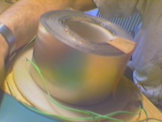
I have used the same coil 2 x 1000 turns with
0.7 mm wire (see above) like a primary coil and I made secundary
coil like a flat spiral coil with 100 turns . For that I used
insulated aluminium strip 67 mm x 0.15 mm. Then the primary
coil was located inside of flat spiral coil.


Interesting to know is that this flat spiral coil has properties of capacitor more than a coil. There are always U/2 from initial voltage on the coil terminals. I made several versions of this transformer and there was always U/2 on the terminals. Just the increased amperage (capacitance) was different.
The number of turns has nothing to do with collecting voltage. It works like a capacitor connected in seria with driving coil/capacitor. With this version we can draw useable current in the same time the current drops on the power source. Bigger capacitance of coil produce more useable current and more current drops from the power source.
For me it makes sense. I believe that if we increase much more capacitance of the flat spiral coil it will produce more current drops from the power source, but the voltage will decrease with the number of turns. For example if we have 300 nF capacitance of the flat ,spiral coil it will make current drops almost to the zero on the power source, but there will be less voltage on the flat coil terminals.
But it is not confirmed yet. It works out of our logic sometimes and I will not be surprised if there will be different results.
Here are modified coils which could be evidence for my words. I made this coil like the drawing showes:

As you can see that I have added Iron core to lead EM field through the flat spiral coil.
When we look this picture we could say that when the flat coil is not short connected or without load connected there is one value of current from the power source. When the flat coil is short connected, then it will assist for closing EM filed lines ( Remember the experiment with SMEP on the Naudin’s Site). According to what you saw above on this page, you will say, that then will be current drops .
But not.. It will increase current from the power source and the bulb will not light. When I removed the iron core it worked like I described many times. It drecrease current from the power source and the bulb light very bright.
The question could be :”Why does closed flux change reaction?”
The answer could be: The Flat spiral Coil needs to be opened for collecting something from the ambient. It could be, but it must be proven.
For your information current was about 120 mA when the flat coil wasn’t under load and later the current was about 70 mA, when the flat coil was under load. I will present more results, when new flat spiral coil will be finished.
V-VERSION
The only difference is that I replaced the flat spiral coil with an ordinary solenoid made by 0.35 mm wire with 5000 turns.


This HV transformer produces over 1000 V on the secundary coil.
The current from the power source was about 120 mA , when the secundary coil wasn’t under load and 50 mA when the fluo tube 15 W was connected on the secundary coil.
The fluo tube light very bright.
Later I made a test with a charging 10 microF capacitor . It charged the capacitor over 1000 V for cca 20 secunds.
This version works oposite than A VERSION. If I use a solenoid with less number of turns, it will produce current drops almost to the minimum on the power source, but there will be little energy stored in the secondary solenoid.
INTERESTING TO KNOW:
You must prepared that it will not work stabile always.
Sometimes there will be current 10 times less than ususal, but it will not change ouput power. But smetimes it will make that you will charge with the same coil; the same resonant frequency; the same capacitor faster then before. This effect comes and goes suddenly.
Also it is very important to notice that it changes phase current :voltage.
See again the pictures from above when maximum current was 20 mA. FYI current for this coil is sometimes 100 mA, sometimes 120 mA and sometimes 150 mA.
Sometimes your bulb will light much better with 10 mA current than with 150 mA. Also you can notice that the light looks strange. I can’t explane this by words.
See the pictures again:


Notice that the peaks from the minimum current are not in the phase with the voltage. Some people said that it could be an evidence for NO-Hertzian( Tesla’s) waves, because there the effect comes later then the causation.
The experiments are not finished. More will come.
COPY RIGHT -
Milan Manchich
01. July 2001.
![]() [email protected]
[email protected]
Return to Tesla Exploration home page